What is the correct procedure to modify the discharge opening of a jaw crusher to control product size?
To adjust a jaw crusher gap, first clear the chamber and perform Lockout/Tagout (LOTO) procedures. Depending on the machine type, either add/remove shims behind the toggle seat, adjust the wedge blocks via a lead screw, or input the target Closed Side Setting (CSS) into the hydraulic control panel. Finally, verify the adjustment by measuring the Open Side Setting (OSS) and calculating the stroke difference.
What preparations are required before starting the adjustment?
Before you grab your wrenches to change the Close Side Setting (CSS), what essential safety and prep steps must happen first?
Before adjusting a jaw crusher gap, you must clear all material from the crushing chamber to ensure the movable jaw travels freely. Next, strictly follow Lockout/Tagout (LOTO) protocols to isolate all power sources and physically block the flywheel to prevent accidental rotation. Finally, visually inspect the crusher to confirm if your specific model uses a shim, wedge, or hydraulic adjustment system so you can gather the correct tools.
Clearing material from the crushing chamber
You cannot accurately adjust the gap if rocks are trapped between the jaw plates. The movable jaw needs to swing fully forward and backward without obstruction. If material remains in the chamber, it acts like a physical stop. This prevents the adjustment mechanism from reaching the correct setting.
Therefore, the first step is to run the crusher until the chamber is completely empty. Stop the feed conveyor first. Then, allow the jaw crusher to run for several minutes. This ensures all remaining stone is crushed and discharged.
Industry Warning: Never attempt to clear a jammed rock by hand while the crusher is idling. This is a severe safety violation that causes critical injuries.
If a blockage persists after running the cycle, you must shut down the machine completely. Use a hydraulic breaker ram or a pry bar only after the machine is fully stopped and locked out. Think of this like tensioning a conveyor belt; you cannot adjust the take-up pulley correctly if the belt is buried under a pile of heavy aggregate. You must remove the load to set the tension accurately.
Executing Lockout/Tagout (LOTO) safety procedures
Jaw crushers operate with immense force. Consequently, ensuring the machine cannot start during maintenance is non-negotiable. The Lockout/Tagout (LOTO) procedure creates a “zero energy state.”
First, shut down the main electric motor. Go to the electrical control room or the local isolator switch. Turn the switch to the “OFF” position. Afterward, place your personal padlock on the switch hasp. Attach a tag with your name and the date. This informs other operators that maintenance is in progress.
However, electrical power is not the only danger. Jaw crushers possess heavy flywheels that store kinetic energy. Even with the power off, the jaw can move unexpectedly if the flywheel rotates due to gravity or imbalance.
Required Safety Steps:
- Electrical Isolation: Lock the main breaker.
- Block the Flywheel: Use a safety bar or chain to physically secure the flywheel to the frame.
- Release Hydraulic Pressure: If your unit has hydraulic assists, bleed the pressure back to the tank.
Note: Specific LOTO locations and blocking points vary by manufacturer. Always consult the specific Lockout/Tagout (LOTO) protocols and operation manual to locate the exact isolation points for your machine model.
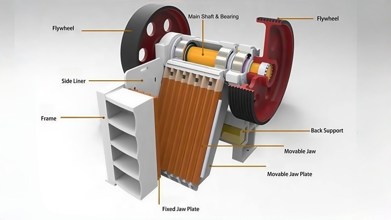
Identifying the specific adjustment mechanism (Shim, Wedge, or Hydraulic)
Once the machine is safe, you must confirm which adjustment system your crusher uses. This determines the tools you need to bring to the platform. Different models require vastly different approaches. You do not want to waste time looking for hydraulic controls on a manual shim crusher.
Inspect the area behind the toggle seat (the back of the machine). The physical components visible there will reveal the type.
Visual Identification Guide:
| Adjustment Type | Visual Indicator | Tooling Required |
|---|---|---|
| Shim (Gasket) | A stack of steel plates behind the toggle block. Large visible bolts holding the block in place. | Heavy wrenches, pry bars, lifting device for plates. |
| Wedge Block | A horizontal screw or hydraulic cylinder mounted sideways on the frame. No stack of plates. | Ratchet wrench for locking bolts, adjustment handle. |
| Hydraulic | Large hydraulic cylinders pushing directly on the toggle. Electrical lines connecting to a sensor. | Control panel key, touch screen access. |
For example, a Shim system functions like adding spacing washers to a bearing housing to set endplay. You physically add metal to close the gap. In contrast, a Wedge system utilizes the inclined plane principle; sliding a component sideways pushes the mechanism forward. Identifying this early ensures you have the correct wrenches or hydraulic pumps ready before you start the actual work.

How to adjust the gap using the Shim (Gasket) system?
What is the step-by-step process for mechanically altering the Closed Side Setting (CSS) on a shim-adjusted jaw crusher?
To adjust the gap using a shim system, first loosen the tension rod spring to release the pullback force. Next, activate the maintenance hydraulic jacks to push the toggle seat forward, creating space. Then, insert or remove steel shim plates behind the toggle block to reach the desired thickness. Finally, depressurize the jacks and re-tighten the tension rod spring to secure the mechanism.
Loosening the tension rod spring nuts
The tension rod acts as a safety tether. It keeps the pitman and toggle plate firmly pulled against the toggle seat, preventing them from separating during the return stroke. Before moving the adjustment block, you must release this holding force.
Start by locating the tension rod at the rear or bottom of the crusher. Use a wrench to loosen the locking nut and the adjusting nut on the spring. You do not need to remove the nut completely. Simply back it off enough to allow the toggle block to slide forward.
Think of this like loosening the motor base bolts before adjusting the V-belt tension on a drive system. If the base is locked down tight, you cannot slide the motor to change the belt tightness. Similarly, if the tension spring is fully compressed, it fights against the adjustment jacks.
Note: The tension spring stores significant energy. Always stand to the side of the rod, never directly behind it, to avoid injury if the rod fails.
Activating the hydraulic jacks to open the toggle seat
Once the spring is loose, you need to create space to handle the shims. Most modern shim crushers feature small hydraulic jacks built into the adjustment assembly specifically for this maintenance task. These are different from the main crushing cylinders found on hydraulic crushers.
Connect the manual pump or activate the electric power pack for these maintenance jacks. As you pump pressure into the system, the jacks extend. This force pushes the toggle seat (the block that holds the back of the toggle plate) forward towards the crushing chamber.
Consequently, a gap opens up between the toggle seat and the rear frame of the crusher. This gap is the “shim slot.” You must extend the jacks far enough to easily remove the existing shims or to fit new ones in.
Adding or removing shim plates to achieve the desired width
This is the critical step where the actual “sizing” happens. The shim stack determines the position of the toggle seat.
- To Decrease the Gap (Finer Product): Add more shims into the slot. Adding shims pushes the toggle seat and the movable jaw forward. This reduces the distance between the jaws.
- To Increase the Gap (Coarser Product): Remove shims from the slot. Removing shims allows the toggle seat to sit further back. This increases the distance between the jaws.
Shim Adjustment Logic Table
| Desired Outcome | Action Required | Effect on Movable Jaw |
|---|---|---|
| Smaller Product size | INSERT Shims | Pushes jaw closer to fixed jaw |
| Larger Product size | REMOVE Shims | Allows jaw to move away from fixed jaw |
| Compensate for Wear | INSERT Shims | Restores original gap after liner wears down |
Note: Standard shim plates typically range from 5mm to 20mm depending on the machine size, allowing for relatively precise adjustments.
Releasing hydraulic pressure and retightening the tension rod
After you arrange the correct stack of shims, the machine parts must be locked back together. The shims are loose, and the toggle seat is floating on hydraulic pressure.
First, open the release valve on the hydraulic jack pump. This bleeds the pressure off. Gravity and the weight of the jaw will settle the toggle seat backward until it rests solidly against the new stack of shims. Ensure the shims are seated flat and are not pinched at an angle.
Finally, return to the tension rod. Tighten the spring nut back to the manufacturer’s specified compression length. This is vital. If the tension rod is too loose, the toggle plate may fall out of its groove or “hammer” against the seat during operation, damaging the machine. The system must be rigid before you restart operations.
How to adjust the gap using the Wedge Block system?
How does the wedge block mechanism function to alter the crusher’s discharge setting?
To adjust a wedge block system, first loosen the lateral locking bolts on the crusher frame to release the clamping force. Next, rotate the adjustment screw or engage the hydraulic assist to slide the twin wedges together or apart. This movement pushes the toggle seat forward to close the gap or pulls it back to open it. Finally, re-torque the locking bolts to rigidly secure the new setting before resuming operation.
Loosening the lateral locking bolts on the frame
Unlike the shim system, the wedge system relies on friction to hold its position during operation. Heavy-duty bolts clamp the crusher side frames tight against the internal wedge assembly. Therefore, you cannot move the wedges while these bolts are tight.
Locate the large locking bolts on the exterior side of the crusher frame. These are usually positioned near the toggle block area. Using a pneumatic impact wrench or a high-torque hand wrench, loosen these bolts. You do not need to remove them completely.
Think of this like adjusting the tailstock on a manual lathe. You must flip the locking lever to release the clamp before you can slide the tailstock along the bedways. If the clamp remains tight, the adjustment mechanism will bind or break. Only loosen the bolts enough to allow the internal wedges to slide freely.
Operating the mechanical screw or hydraulic assist to move wedges
Once the frame is unclamped, you can move the wedges. This system uses two tapered blocks. One block remains stationary relative to the toggle seat, while the other slides vertically or horizontally.
- Mechanical Screw: You manually turn a lead screw using a ratchet or handle. Rotating the screw moves the sliding wedge.
- Hydraulic Assist: A small hydraulic cylinder pushes or pulls the wedge. This removes the physical effort of turning a screw but still relies on the wedge geometry to hold the load.
Wedge Movement Guide
| Desired Gap Change | Wedge Action | Mechanical Result |
|---|---|---|
| Close the Gap (Smaller CSS) | Push wedges together (increase overlap) | The combined thickness increases, pushing the jaw forward. |
| Open the Gap (Larger CSS) | Pull wedges apart (decrease overlap) | The combined thickness decreases, allowing the jaw to retract. |
As the wedges overlap more, they occupy more space. Consequently, they push the toggle seat forward toward the crushing chamber. This reduces the Close Side Setting (CSS). Conversely, separating the wedges reduces their total thickness, retracting the toggle seat.
Industry Note: Hydraulic assist wedges differ from full hydraulic systems. Here, the hydraulics only move the wedge; the metal wedge itself holds the crushing force, not the oil pressure.
Verifying the movable jaw position
Since wedge systems are infinitely adjustable (stepless), unlike shims which have fixed thicknesses, you must watch the movement carefully. It is easy to overshoot your target setting.
As you turn the screw or activate the hydraulic assist, observe the pitman or the toggle seat. Ensure it is actually moving. Sometimes, if the machine is old, the wedge surfaces may be sticky with dried grease or dust.
If you are aiming for a specific change, such as closing the gap by 10mm, measure the travel of the wedge drive rod. However, the ratio is not always 1:1. A 10mm movement of the wedge might only result in a 3mm movement of the jaw, depending on the taper angle.
Re-torquing the locking bolts to secure the setting
After achieving the desired position, you must lock the system down. The wedge prevents the jaw from moving backward, but the locking bolts prevent the wedge itself from vibrating loose.
Return to the side locking bolts you loosened in the first step. Tighten them to the manufacturer’s specified torque settings. Use a cross-pattern sequence if there are multiple bolts to ensures even clamping pressure.
If these bolts remain loose, the constant vibration of crushing rock will cause the wedges to “walk” or slip. This effectively changes your gap setting while the machine is running. It creates a similar risk to leaving the lug nuts loose on a haul truck wheel; eventually, the assembly will fail under load. Ideally, use a calibrated torque wrench to confirm they are secure.
Hydraulic Cylinder System Adjustment Procedure
How does the automated hydraulic system change the discharge setting without manual tools?
To adjust a hydraulic cylinder system, access the machine’s Programmable Logic Controller (PLC) via the touchscreen interface. Next, input your desired Closed Side Setting (CSS) value directly into the digital control field. Then, initiate the automatic calibration cycle, allowing the hydraulic rams to physically reposition the toggle beam. Finally, monitor the display for confirmation messages or error codes to verify the new setting is locked.
Accessing the settings via the PLC touch screen or control panel
Modern hydraulic crushers replace physical wrenches with digital interfaces. You must interact with the Human Machine Interface (HMI) located in the control cabin or on the power unit. This screen acts as the brain of the crusher.
First, ensure the control power is on. Navigate to the “Settings” or “Maintenance” menu on the touch screen. Most systems require a specific user level to change parameters. You likely need an “Operator” or “Administrator” password. This prevents unauthorized personnel from altering critical machine settings.
Think of this like accessing the parameters on a Programmable Logic Controller (PLC) for a conveyor motor. You cannot simply turn a physical dial; you must log in, find the correct parameter group, and input the digital data. If you cannot access the menu, check if the Emergency Stop button is depressed, as this often locks the software interface.
Inputting the target Closed Side Setting (CSS) value
Once inside the adjustment menu, you will see a field labeled “Target CSS” or “Set Point.” Unlike shim systems where you calculate plate thickness, here you simply type the desired output size.
Enter the specific millimeter or inch value you require. For example, if you need a 75mm product, type “75”. The computer calculates the necessary cylinder movement.
Industry Warning: The system has hard-coded safety limits. If you try to input a CSS smaller than the manufacturer’s minimum (e.g., 40mm), the system will reject the value. This prevents the moving jaw from colliding with the fixed jaw.
Running the automatic calibration cycle
After entering the value, press the “Start” or “Adjust” button. The machine takes over from here. You will hear the hydraulic pump ramp up pressure.
The hydraulic cylinders behind the toggle plate will extend or retract. On many advanced units, the system performs a “Zeroing” or “Calibration” sequence first. It may fully close the jaw to find the zero point (where dies touch) and then retract to your set number. This ensures accuracy.
This process is similar to the automatic zero-calibration performed on a conveyor belt scale. The system must find its physical reference point before it can measure and adjust accurately. Do not interrupt the power during this cycle. Doing so can cause the system to lose its position memory, requiring a manual reset.
Monitoring the system for error codes during adjustment
While the hydraulics are moving, keep your eyes on the screen. The system uses sensors, often Linear Variable Differential Transformers (LVDT), to measure the cylinder position.
If the movement is too slow or the pressure gets too high, the PLC will stop the process to protect the seals. It will display an error code. You must understand what these codes mean to troubleshoot effectively.
Common Hydraulic Adjustment Status Codes
| Status Message | Meaning | Required Action |
|---|---|---|
| Target Reached | The cylinders are in position and locked. | Safe to resume crushing. |
| Pressure Fault | Hydraulic resistance is too high. | Check for material jammed in the chamber. |
| Sensor Error | The PLC cannot “see” the cylinder position. | Inspect the sensor cables for damage. |
| Out of Range | Input value exceeds machine limits. | Enter a value within the valid CSS range. |
If the screen shows “Target Reached,” the hydraulic valves will close to lock the oil in the cylinders. This creates a rigid hydraulic lock, similar to a check valve, holding the jaw in place against the crushing forces. Only then is the machine ready for operation.

How do you verify the gap setting is correct?
After mechanically moving the jaw, how can you be certain the discharge opening matches your production requirements before feeding rock?
To verify the gap setting, manually measure the distance between the jaw dies at the bottom of the chamber while the machine is stationary to obtain the Open Side Setting (OSS). Next, subtract the specific eccentric stroke value of your machine from this measurement to calculate the actual Closed Side Setting (CSS). Finally, conduct a brief load-free test run to confirm the assembly is tight and operating without vibration.
Measuring the Open Side Setting (OSS) with a gauging tool
You cannot safely measure the Closed Side Setting (CSS) while the crusher is running. The moving jaw oscillates too fast. Therefore, you must measure the gap when the machine is stopped and locked out.
At rest, the movable jaw hangs naturally in its open position due to gravity and the pullback rod. This static measurement is called the Open Side Setting (OSS). To get an accurate reading, use a specialized CSS gauging tool. This tool looks like a set of calipers or a heavy-duty “wand” with a measuring head.
Lower the tool into the bottom of the crushing chamber. Measure the distance between the “peak” (tooth tip) of the fixed jaw die and the “valley” (tooth root) of the movable jaw die. Do not rely on a simple tape measure, as it is difficult to keep straight inside a deep chamber.
Industry Note: Some manufacturers define the measurement point as “tooth peak to tooth peak,” while others use “peak to valley.” Always verify the specific measurement standard with your liner supplier to avoid a 10-20mm error in your product size.
Converting OSS to Closed Side Setting (CSS) based on stroke
Once you have the OSS number, you must do some math. The OSS is not your crushing size. Your actual crushing size happens when the jaw closes tightest during operation (CSS).
The difference between the open position and the closed position is the “Stroke” (or Throw) of the eccentric shaft. To find your true setting, use this simple formula:
Formula: CSS = OSS - Eccentric Stroke
For example, if you measure an OSS of 125mm and your machine specification states a stroke of 35mm, your actual operating gap (CSS) is 90mm. This calculation is critical. If you assume the OSS is your final size, your product will be significantly finer than expected, potentially overloading the conveyor belt.
Typical Verification Calculation Table
| Measured OSS (Static) | Machine Stroke (Fixed Spec) | Calculated CSS (Dynamic) | Result |
|---|---|---|---|
| 100 mm | 25 mm | 75 mm | Product size approx. 75mm |
| 125 mm | 25 mm | 100 mm | Product size approx. 100mm |
| 150 mm | 30 mm | 120 mm | Product size approx. 120mm |
Performing a short load-free test run
The numbers may look correct on paper, but you must verify the mechanical integrity physically. Before dumping tons of stone into the hopper, perform a “dry run.”
Clear all personnel from the immediate area. Start the crusher motor and let it run empty for about 10 to 15 minutes. Listen intently. You are checking for “knocking” or “clacking” sounds.
If the tension rod was not tightened sufficiently after the adjustment, the toggle plate will detach slightly from its seat on every rotation. This creates a distinct metallic knocking sound. It is similar to the sound of a loose connecting rod in a diesel engine (often found in site generators or haul trucks).
Additionally, monitor the bearing temperatures. If you adjusted the gap too tight (below the manufacturer’s minimum CSS), the friction will cause the bearings to overheat rapidly. If the machine runs smoothly and quietly during this test, it is safe to resume full production.
Conclusion
Properly adjusting the jaw crusher gap is not merely about changing the product size; it is a critical maintenance routine that directly impacts the longevity of the wear parts and the overall efficiency of the plant. Whether you are manually stacking shims or operating a touch-screen hydraulic system, the fundamental principles remain the same: prioritize safety through LOTO procedures, understand the difference between CSS and OSS, and always verify the final setting before full operation. By mastering these adjustment techniques, you ensure consistent aggregate output and minimize costly downtime due to mechanical failures or blockages.